Project intro: Reversing Philips Hue light driver

Introduction
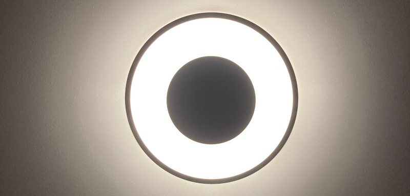
We own several Philips Hue ceiling lights. The “White Ambiance” kind that allows you to change color temperature.
In this multi-week project I will attempt to reverse how the board works, and create my own drop-in replacement PCB.
Background
You might ask yourself – why the hell would anyone (sane) do something like this?
Such a great question! This is not by choice.
We live in a multi-tenant building. And lately some asshat
friendly neighbor of ours decided to mess with our lights.
See, Philips Hue has this idiotic behavior that within 30 minutes of being powered up is pairable over bluetooth by anyone1.
And since we use the dumb wall switch to turn our lights on/off, there’s nothing we can do to prevent trolls from taking over our lights2.
So, it was down to either breaking into the existing chip (its firmware), finding an off-the-shelf replacement that’s not as stupid as Philips Hue, or – reluctantly – writing my own.
Architecture
Basic architecture of the light pictured above is rather simple:
Let’s discuss each:
Power brick
The power brick is tasked with converting 220V AC to 24V DC.
It’s an unassuming 40W (24V 1.67A) jobbie.
Controller board
The controller board takes in 24 V DC, exposes endpoints via Zigbee and Bluetooth, and drives the LED strip.
These controller boards are, depending on the version of the light:
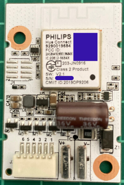
Hue Connect 9290019684
This can be found in the older model of the light (3261031P6).

It is a white board that carries the following inscriptions:
Philips
Hue Connect
9290019684
FCC ID: 2AGBW9290019684X
IC: 20812-9684X
In my case also:
SW: V2.1
S/N: (redacted)
CMIIT ID: 2019DP9206
I don’t have a reasonable picture of the back of the board, but there’s not much on it (besides test-points).
From what I was able to gather, on the back is an unpopulated 8-pin debug header footprint (just like on the Hue Engine board described below) that has SWD and UART broken out, among other things.
The chip under the metal can is probably EFR32MG13, in case you care.
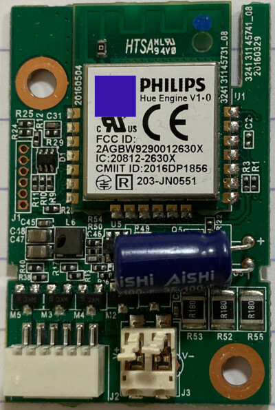
Hue Engine v1.0
This can be found in the newer model of the light (3261031P7).


It is a green PCB board that carries the following inscriptions on the front:
Philips
Hue Engine v1.0
FCC ID: 2AGBW9290012630X
IC: 20812-2630X
CMIIT ID: 2016DP1856
[R] 203-JN0551
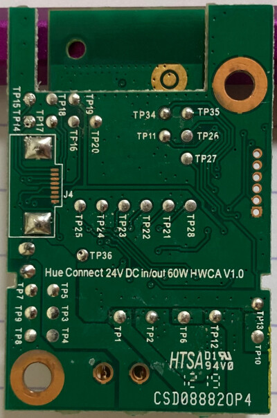
On the back you could also find:
Hue Connect 24V DC in/out 60W HWCA V1.0

CSD08882OP4
LED strip
In the White Ambiance lights, the LED strip is relatively unique – unlike other strips you might find elsewhere.
It has three distinct LED channels. Originally I thought they’re:
- Warm White
- Neutral White
- Cold White
but I’m not so sure anymore. I don’t know the exact color parameters. And at least
one of the channels looks very green-ish to me.
(Update 2025-07-17: Spectrum characterization is in the Philips Hue White Ambiance is actually terrible… post.)
The only visible markings on the strip are 8122 340 28382 and E477885 HQ-D.
It is a common anode strip (24V DC is perma-connected and the PWM channels connect the cathodes to ground or leave them floating).
Plan
The plan is simple:
- Try breaking into the chip on the controller (to modify firmware)
- If that fails, get enough information to recreate the controller
- Design the controller, write firmware
- Profit
Execution
- Part I: Hue Engine: Basic reconnaissance
- Part II: Hue Engine: Dumping the PWM data
- Part III: Hue Engine: Reversing the PWM functions
- Part IV: Zigbee: Hue-llo world!
- Part V: Introducing e32wamb: firmware for esp32-c6 based White Ambiance light)
- Part VI: Final stretch for e32wamb: PCB, cables, antenna holder – v1.0
- Part VII: ESP32 as a Zigbee console
- Part VIII: Philips Hue White Ambiance is actually terrible…
More to come in the future.
-
The full backstory to figuring this out involves me first thinking the light is somehow malfunctioning, contacting support, who had me reset the light, then tell me they can’t help me any further. Then me trying to link the lights to a Bridge (instead of just to the dedicated dimmer), thinking that someone zigbee-linked our lights. And only then realizing that no, in fact the lights have bluetooth, it can’t be disabled, and Philips / Signify doesn’t care. ↩