Anatomy of an Ocean Optics USB-DT (Deuterium-Tungsten Light)
Problem statement
I scored on eBay a “for parts” combo of an Ocean Optics HR4000 spectrometer and a USB-DT (Deuterium-Tungsten light source).
The offer mentioned that the USB-DT doesn’t seem to do anything when powered with 5V.
I decided to buy it and investigate1. Thinking “how hard can it be to make it work?”
This is both a teardown of the hardware, but also a story of how I made it work – mostly by unnecessarily reversing the control protocol.
Preamble: The what?
In case you don’t know what a Deuterium-Tungsten light is about, I think the following spectral profile is useful:
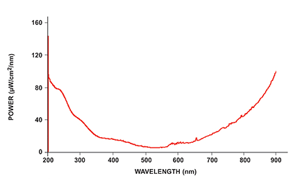 USB-DT spectral power distribution, courtesy of its datasheet
Simply put, the advantage is that it’s a broadband light source covering at least 200..1100 nm range. So, from UVC all the way to Near Infrared.
First impressions
Package arrived shortly, here’s the USB-DT part:
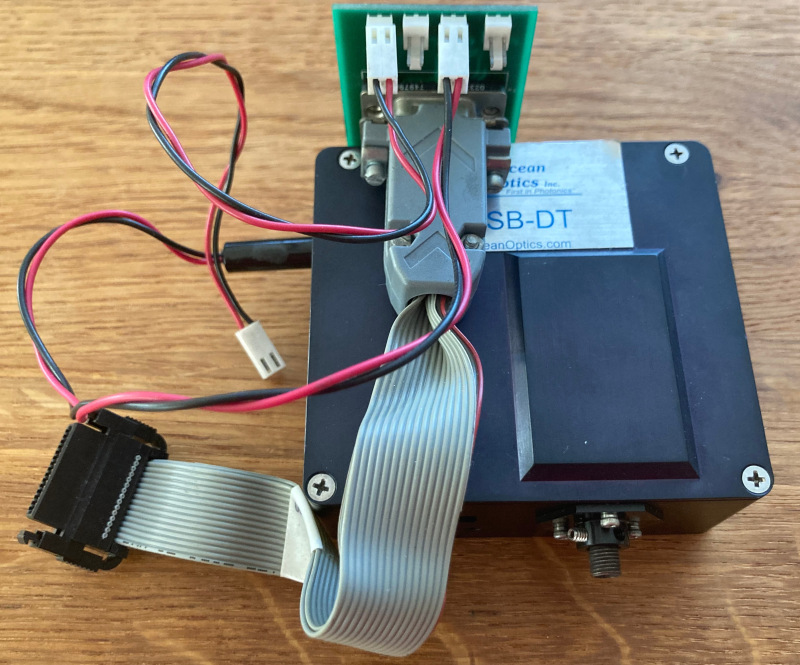 Ocean Optics USB-DT with harness
If you look at a newer generation USB-DT datasheet, you will find it closely matches this unit:
- DB15 port
- 10-pin output connector
- SMA light output
Briefly testing the “HR4” (3M P50-030S-EA) connector (using data from the HR4000 datasheet pinout) against the DB15 + front output connector (and the USB-DT datasheet) using a continuity mode on a multimeter showed me that the pinout matches.
Also, the gray flat cable (marked Ocean Optics 210-40000-000),
that interfaces with HR4000, has the following pinout:
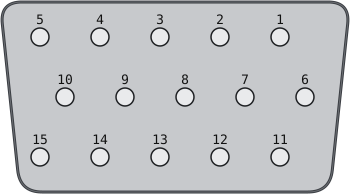 db15 female, looking at it
| DB15 Pin | Description | HR4000 (3M P50-030S-EA) pin |
|---|---|---|
| 1 | Single Strobe | 17 |
| 2 | Continuous Strobe | 20 |
| 3 | V5_SW | 4 |
| 4 | External Trigger In | 10 |
| 5 | External Trigger In | 10 |
| 6 | GPIO(8) | 28 |
| 7 | Analog Out (0-5V) | 24 |
| 8 | VCC, VUSB or 5Vin | 12 |
| 9 | GPIO(9) | 30 |
| 10 | Ground | 29 |
| 11 | I²C SDA | 8 |
| 12 | I²C SCL | 6 |
| 13 | Lamp Enable | 25 |
| 14 | Reserved | 23 |
| 15 | GPIO(7) | 26 |
First contact
Anyway, I tried to power the device on (with 5V)… and nothing happened.
So I thought that maybe it needs a bootstrap from the HR4000.
I connected them together, powered the USB-DT, plugged the HR4000 to USB… and again, nothing. Somewhat worryingly, the spectrometer did not even properly showed up on the USB bus this time around.
Connecting the spectrometer first, and the USB-DT second did not “brick” the spectrometer, but also did not amount to much. Although the following:
# Python
import seabreeze.spectrometers as sb
s = sb.Spectrometer.from_first_available()
s.f.strobe_lamp.enable_lamp(True)
resulted in a resounding “click” (in retrospect: shutter opening). But, no light output.
Teardown
I decided to take a look under its skirt, to check for obvious damage:
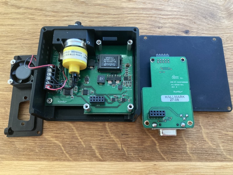 USB-DT with the interface card pulled out
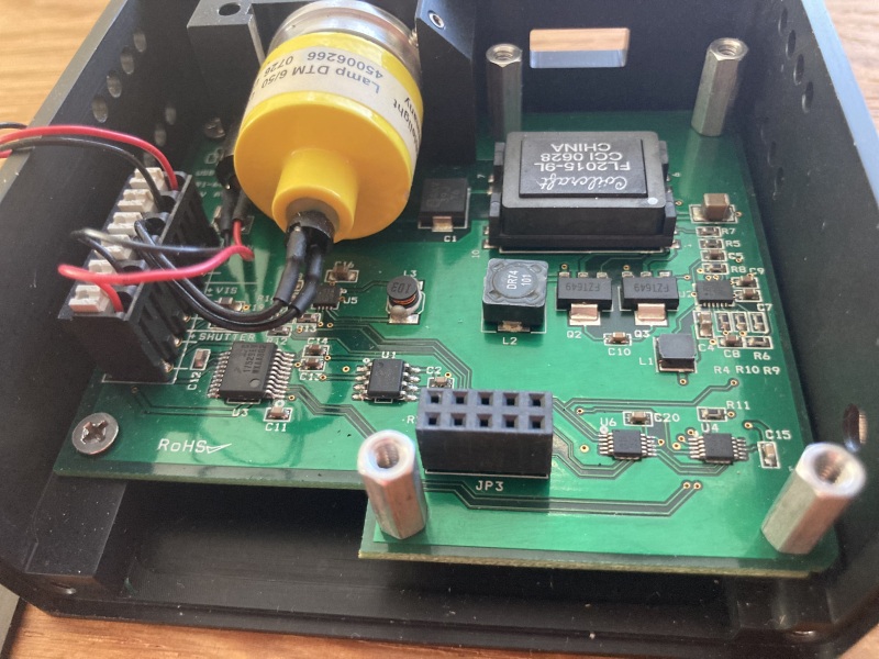 USB-DT closeup of the main board
Let me annotate the main parts:
| Symbol | Part number | Description | Location |
|---|---|---|---|
| Lamp | Noblelight DTM 6/502 | D-T source | the big yellow thing |
| U1 | Microchip 24LC64 | 64Kbit I²C EEPROM | left of the black 2x5 header |
| U2 | Analog LTC3458 | Sync Step-Up DC/DC | right side, in the middle |
| U3 | NXP MPC17529EV | Dual H-Bridge driver | left of U1 |
| U4 | TI DAC5574 | Quad DAC with I²C iface | bottom right corner |
| U5 | Analog LTC3531 (probably) | Buck-Boost DC/DC | under the lamp connector |
| U6 | TI DAC5574 | Quad DAC with I²C iface | left of U4 |
Based on that, it’s safe to say that I²C has some role to play in this device. ;)
Anyway, board looks fine. No scorch marks, etc.
Back to resuscitation.
Resuscitation, round two
I tried replicating the partial success of opening/closing shutter by bringing 5V to the “Lamp Enable” pin. No bueno.
Given that the I²C might be playing a role here, I decided to investigate that path further.
I booted up the HR4000, connected the USB-DT, and proceeded to query (datasheet in hand) things around.
You see, the HR4000 datasheet lists several interesting USB commands:
| Command | Description |
|---|---|
| 0x0B | Query number of Plug-in Accessories Present |
| 0x0C | Query Plug-in Identifiers |
| 0x0D | Detect Plug-ins |
| 0x60 | General I²C Read |
| 0x61 | General I²C Write |
I’ll spare you the boring prose. The following:
import seabreeze.spectrometers as sb
s = sb.Spectrometer.from_first_available()
import struct
# Detect plugins
s.f.raw_usb_bus_access.raw_usb_write(data=struct.pack('<B', 0x0D), endpoint='primary_out')
# Query num of plugins
s.f.raw_usb_bus_access.raw_usb_write(data=struct.pack('<B', 0x0B), endpoint='primary_out')
print("Plugins: " + str(s.f.raw_usb_bus_access.raw_usb_read('primary_in', 1)))
# Query plugin ids
s.f.raw_usb_bus_access.raw_usb_write(data=struct.pack('<B', 0x0C), endpoint='primary_out')
print("Plugin IDs: " + str(s.f.raw_usb_bus_access.raw_usb_read('primary_in', 7)))
outputs:
Plugins: b'\x00'
Plugin IDs: b'\x00\x00\x00\x00\x00\x00\x00'
So, no plugins, and no plugin IDs. Wth?!
What remains is raw I²C I/O.
Resuscitation, round three
This is where things took a dangerous turn.
Let me explain briefly.
Normally, when you scan I²C bus, the way i2cdetect -y 1 would do it, is that
you take addresses between 0x08 and 0x77, and you try a zero-length I²C
write to the addresses.
If you get an ACK, there is a device at that address.
And you could say, well, the HR4000 has a handy 0x61 function:
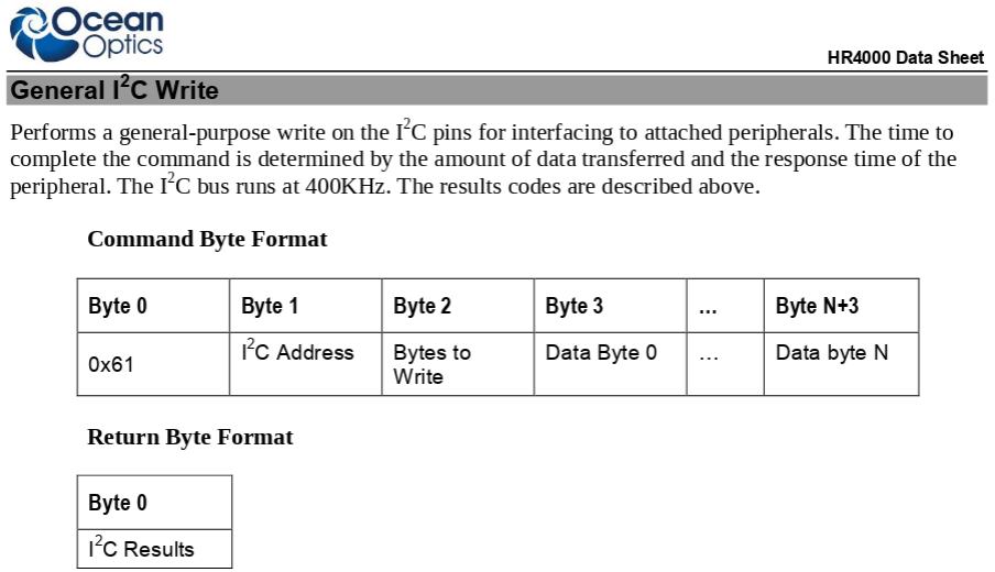 Snapshot of I²C Write USB command from HR4000 datasheet
Well, please don’t (use it for I²C scanning).
Because the HR4000 has a firmware bug3 where if you try writing 0 bytes,
it will actually blast 254 byte long write txn to the target instead, with
garbage data somewhere from its memory.
And since the eeproms holding vital data (like bootloader, or irrad calibration) are siting on that same bus… you really don’t want to do this:
# Python would-be-I²C-probe that will brick your spectrometer
import seabreeze.spectrometers as sb
import struct

print("DO NOT USE THIS. The 0x61 has a bug, where if you say write 0x00 bytes,")
print("  it will blast 0xfe bytes to that device (as long as it acks)!!!")
exit(111) # IYKYK

s = sb.Spectrometer.from_first_available()
for i in range(8, 0x78):
    s.f.raw_usb_bus_access.raw_usb_write(
            data=struct.pack('<BBB', 0x61, i, 0),
            endpoint='primary_out')
    a = s.f.raw_usb_bus_access.raw_usb_read('primary_in', 1)
    if a == b'\x08':
        print(f"address {i} (0x{i:2x}) is live")
Anyway, long story short, I managed to partially overwrite both eeproms in HR4000, and also the eeprom in the USB-DT.
The former two were recoverable, the latter was not, because I don’t know what was in that eeprom4.
I thought things were hopeless at this point.
Resuscitation, round four
While bringing the HR4000 back to health, I also briefly checked on what’s happening on the I²C bus during boot.
Interestingly, the boot activity is roughly as follows:
- try
0x28(fails as there’s no device) - read from
0x51(24LC256 eeprom holding fw and “eeprom slots”) - write
0x51byte to0x4faddress (DS1721 temp sensor) - (try to) write to
0x4cand0x4eaddresses (!!)
The last one, coincidentally matches the addresses that the DAC5574 use
(0b10011.., so 0x4c .. 0x4f).
OK, but in that case, why wouldn’t the USB-DT come online?
Turns out, I was using dinky unshielded USB-A to USB-B cable.
And somehow the bringup of the USB-DT soft-bricked the HR4000. That’s why it wasn’t showing up on the USB bus!
And the USB-DT should also be on the I²C bus before you power on the HR40005.
When I replaced the USB cable, the USB-DT fan started spinning immediately after I plugged in the HR4000 USB cable.
The activity on I²C was:
...
- write 0x4F (DS1721):
  0x51        (start temp conversion)
- write 0x4C:
  14 3B 00    (set channel C to 0x3B)
  16 00 00    (set channel D to 0x00)
  10 A5 00    (set channel A to 0xA5)
  12 00 00    (set channel B to 0x00)
- write 0x4E:
  12 A5 00    (ch B to 0xA5)
  14 00 00    (ch C to 0x00)
  16 00 00    (ch D to 0x00)
  10 FF 00    (ch A to 0xFF)
- write 0x4C:
  10 A5 00    (ch A to 0xA5)
  12 00 00    (ch B to 0x00)
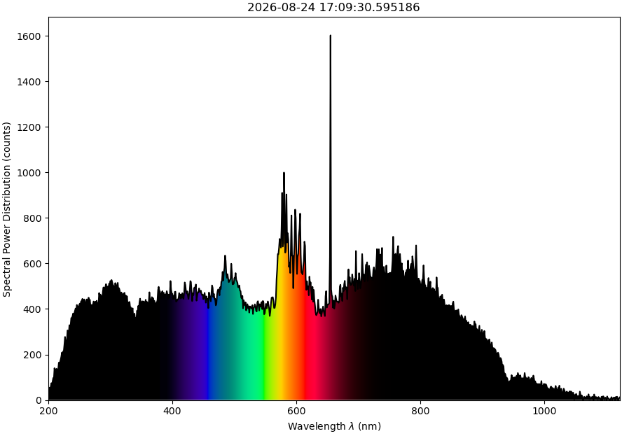
And after s.f.strobe_lamp.enable_lamp(True)… voilà:
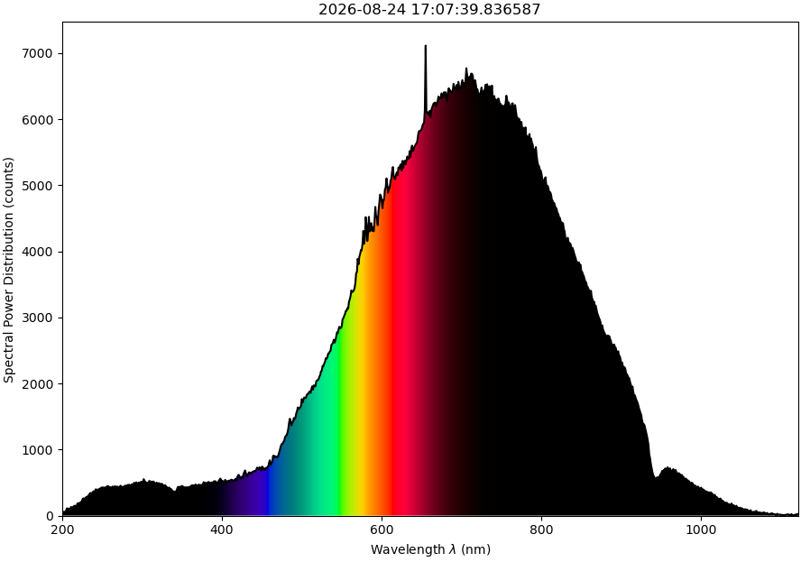 First light! Isn’t she a beauty? 200nm to 1000nm+
To finish documenting this, running the s.f.strobe_lamp.enable_lamp(True)
does:
- write 0x4c: 10 00 00
- write 0x4c: 12 A5 00
and the s.f.strobe_lamp.enable_lamp(False) does the opposite:
- write 0x4c: 10 A5 00
- write 0x4c: 12 00 00
Internal wiring
Encouraged by that result, I traced the output channels of the two DAC5574s.
Unless I made a mistake:
right DAC5574 (address 0x4C):

outA -- MPC17529EV in1A (shutter+ via hbridge)
outB -- MPC17529EV in1B (shutter- via hbridge)
outC -- vis (tungsten)
outD -- NC?

---

left DAC5574 (address 0x4E):

outA -- deuterium driver (U2) + dc/dc (U5) (?)
outB -- MPC17529EV in2A (fan via hbridge)
outC -- NC?
outD -- NC?
The 0x4c outC channel (by default 0x3b) is interesting, because it
seems to allow controlling the brightness of the Tungsten:
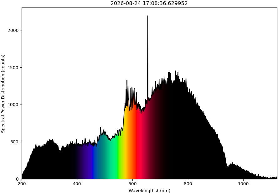
0x4c channel C set to 0x8b
0x4c channel C set to 0xab
Closing words
I think I messed up on several fronts:
- Unshielded USB cable
- Botched I²C scan (that hit a firmware bug of the HR4000)
- Corrupted eeprom on the USB-DT
But all is well that ends well. The USB-DT works (despite the overwritten eeprom), and I learned quite a bit about internals of Ocean Optics gear.
You can read all about the HR4000 firmware bug in a follow-up post: I²C Write Bug in Ocean Optics Spectrometers.
-
It was less of a gamble than you might think, mostly because the HR4000 showed up as a USB device, so it was unlikely they would be both dead on arrival. ↩
-
Can’t find a datasheet, and not for lack of trying. ↩
-
See I²C Write Bug in Ocean Optics Spectrometers post. ↩
-
I tried reaching out to some Ocean Optics folks, but so far no luck. ↩
-
Well, it doesn’t, if you do all the bringup work manually. Which you could; read on. ↩