Final stretch for e32wamb: PCB, cables, antenna holder
 Spoiler: one of the e32wamb alive.
Introduction
This is the sixth post in the Reversing Philips Hue light driver series.
In the fifth part, I talked about the firmware part.
Overview
After writing the firmware for my zigbee light-to-be, the next step are the physical bits: PCB, cables, and antenna holder.
All leading to v1.0, at the bottom of the post. :-)
The PCB
The PCB was relatively straightforward. I already settled on Seeed Studio’s XIAO ESP32C6 as a ready-made module. In part because it’s small but also because it sports a u.fl connector for external antenna1.
So all it took, essentially, was 24V-to-3V3 voltage regulator, mosfet driver, and a few things like RGB LED diode and a reset button2.
Since I knew basics of KiCad from before, it was super easy, barely an inconvenience:
 Schema
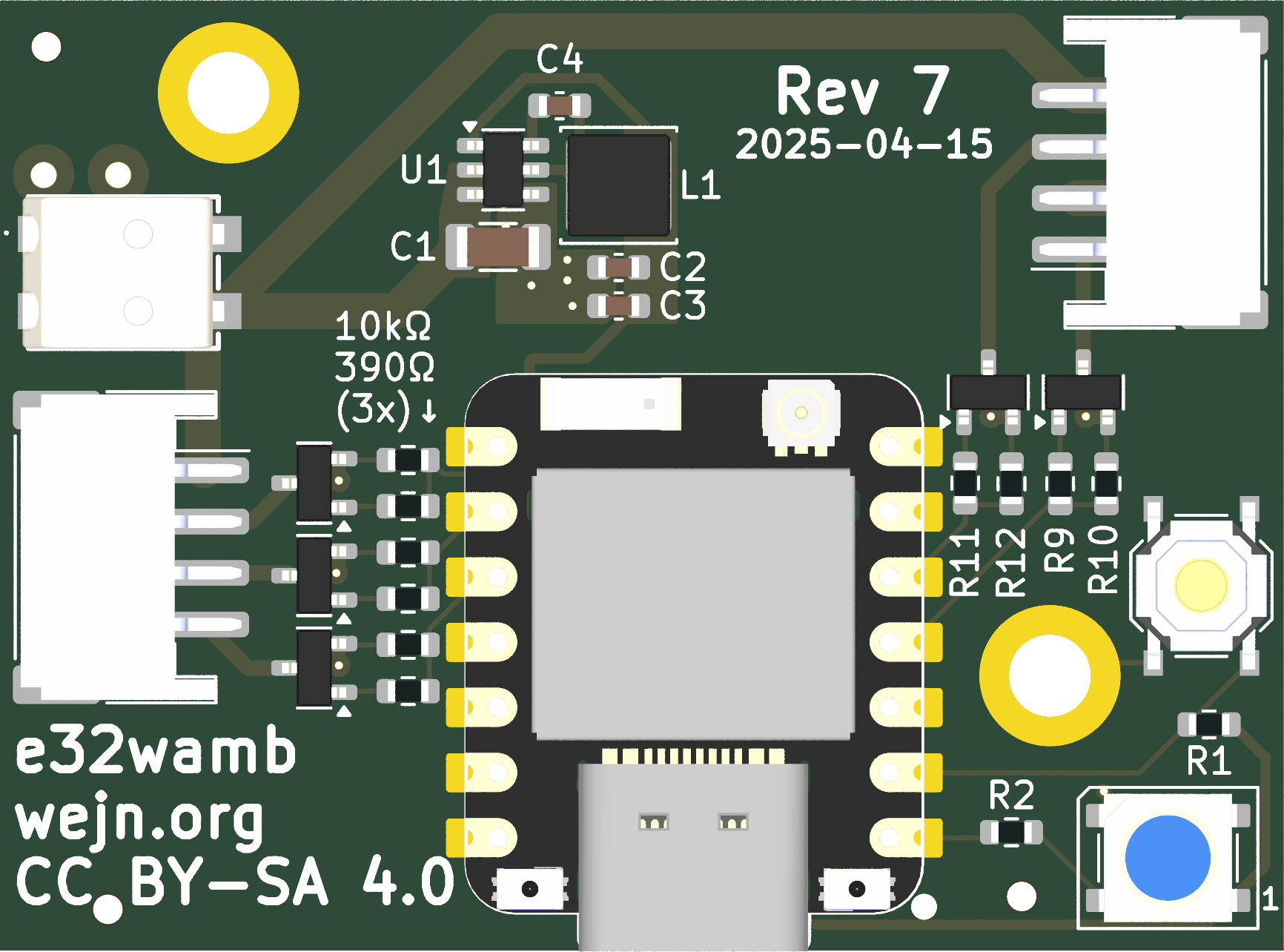 PCB front
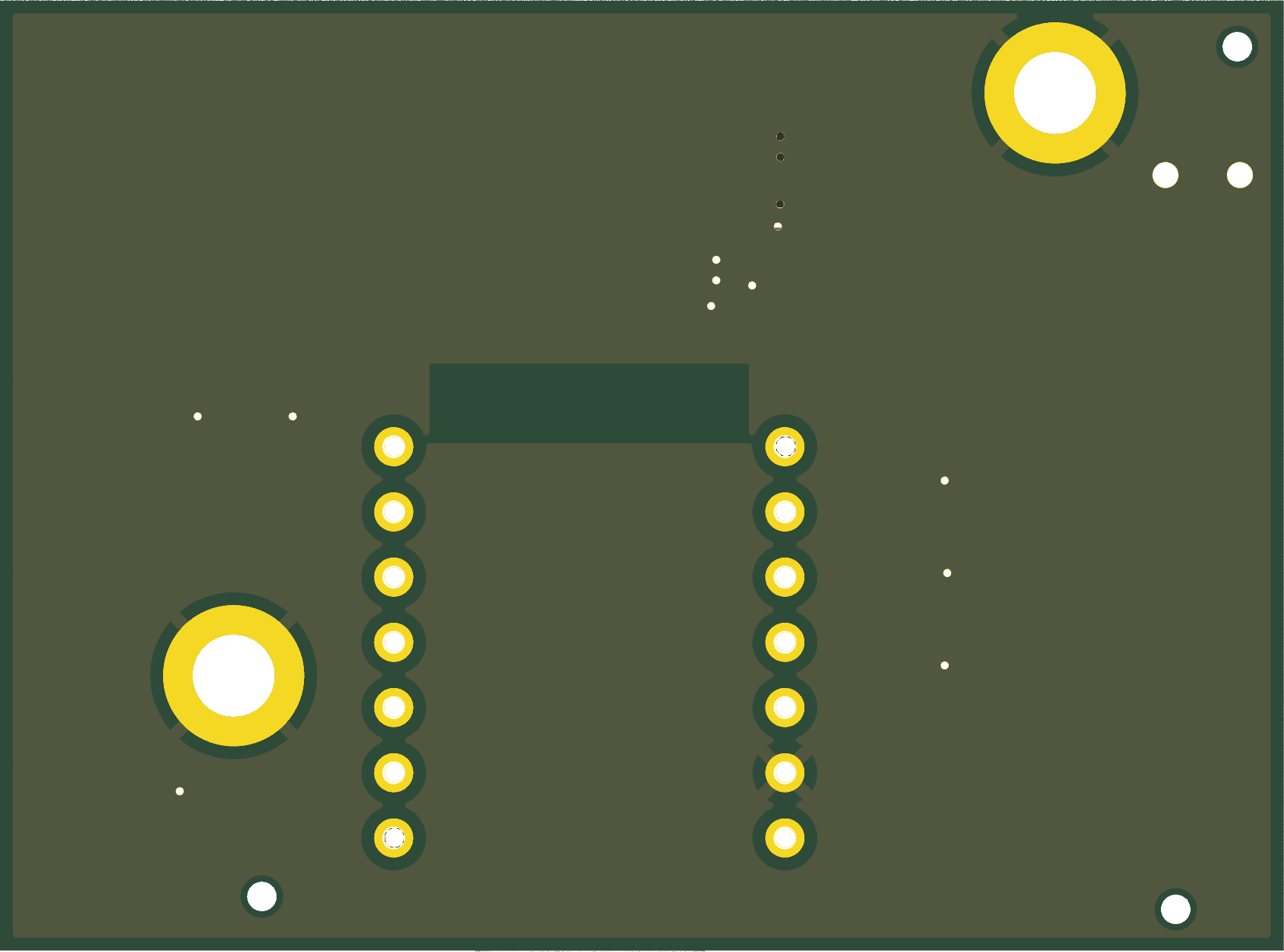 PCB back
Actually, if you look at the e32wamb-pcb repo you will be able to tell that I’m lying my little ass off. There’s 30 commits spanning roughly 10 days.
And that’s after I settled on some of the basics like: which voltage regulator and mosfets to use, which headers, etc.
KiCad automation
Since I last looked at KiCad3, it went from very version control unfriendly to having git as a first class citizen.
On top of that, KiCad 9 has nice support for kicad-cli
which allows lightweight Makefile-based automation
of PCB / schema export, etc.
It’s plenty nice for a start, with more involved solutions like KiBot available when one outgrows the basics.
Component selection
The components I was choosing from were all from LCSC because I didn’t want to assemble the PCBs by hand4; I wanted to use JLCPCB’s assembly service. And JLCPCB either sources from LCSC, or is the same company. IDK for sure.
With that, I was looking at AP64352SP-13, LMR51420XDDCR, AP63200WU-7, AP63203WU-7.
And in the end chose the AP63203WU7 (LCSC ID: C780769) because it was fixed and had a great datasheet (easy to understand, unlike the TI’s for LMR51420XDDCR wrt layout).
For the mosfet, I think I chose poorly – I thought a JLCPCB basic part (no name AO3400-HXY, 30V 5.8A) would be fine and save me something in setup costs5. It works OK, but I haven’t saved anything.
And surprisingly, when I accidentally shorted the 24V through the mosfet, it burned like paper before the PSU’s overcurrent protection kicked in. Sigh. The mosfets on Hue board don’t have that problem – AMHIK. ;)
Other components I mainly chose by physical constraints (JST PH has 2.0mm pitch, which is compatible with the Philips LED strip headers) and comfort level – WS2812 is an old friend, and the (relatively) giant reset button is just pleasant to press, unlike the microscopic jobbies on the XIAO.
Assembly
The hoops to jump through for assembly were surprisingly few.
I have found the jlc-fab-toolkit KiCad plugin that works great with a bit of wrestling even from CLI.
All it needed are LCSC and optional FT Rotation Offset
properties on the parts, and it spits out zip with gerbers,
BOM.csv and positions.csv (CPL), which is all one needs to
get the PCB directly made and assembled:
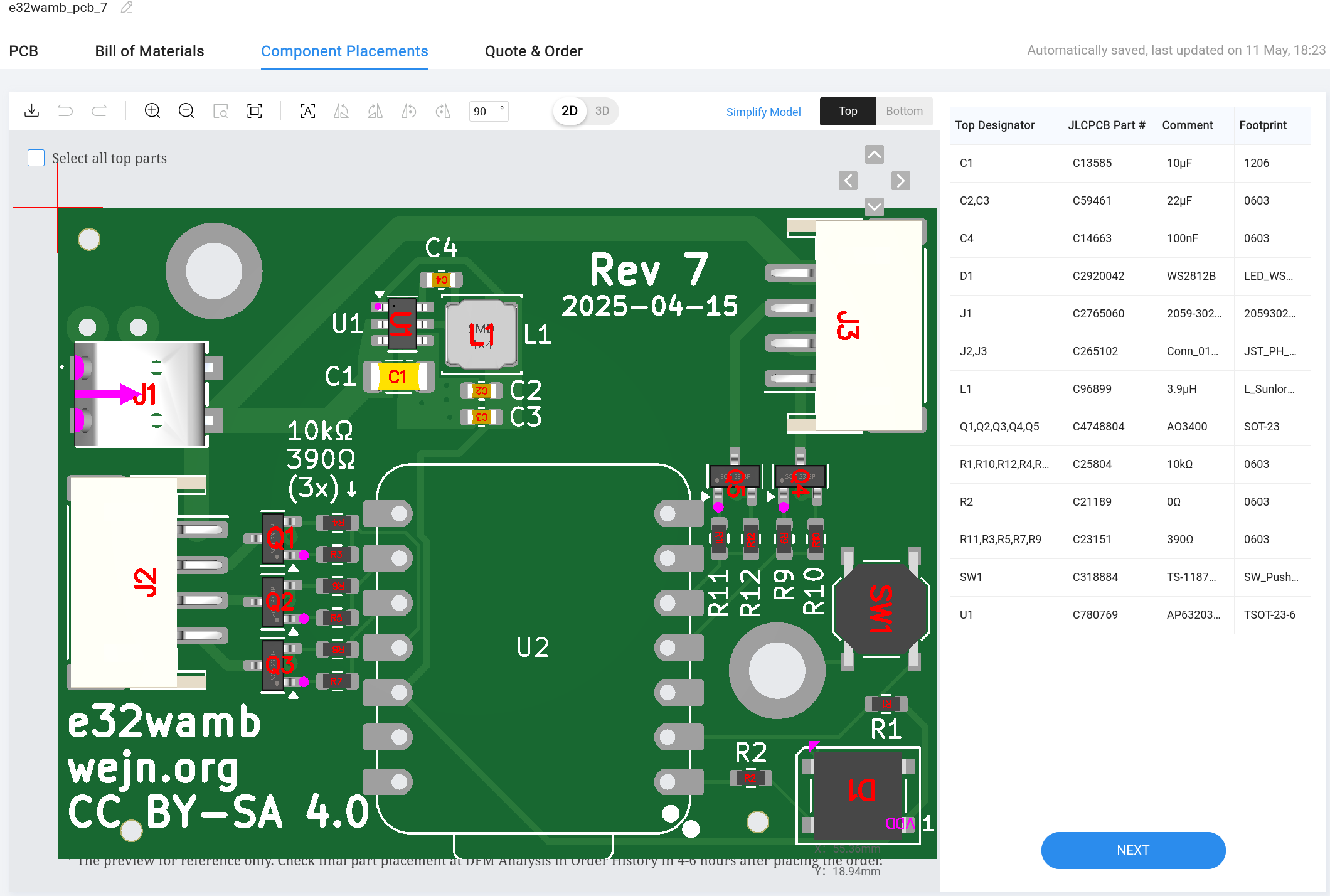 JLCPCB components placement overview
PCB review
As this was my first “real” board, I asked a few folks for review before fabbing. Hell, I even asked on reddit.
Some of the private reviews were helpful, but I still feel I don’t have a good answer for getting consistently useful reviews for the next project.
What went wrong
I played it very fast and loose with the silkscreen. And
I’m a dumbass for not including + and - description
on the Wago power input connector.
Similarly, as I’ve alluded above, the mosfet selection was rather sub-optimal. Maybe I should have chosen a bit more expensive part, but one that would survive direct short6.
Another thing I would avoid doing in the future is using a 3rd party module I have to solder on myself. It’s not a big deal, even when I need to solder 6 of them, but it’s nowhere near “pleasant” territory7. So throwing on ESP32-C6-MINI-1U would cost some more time to design properly but would also avoid the hand soldering hassle.
Lastly, for bigger series than the 10 I ordered, having an automated end-to-end test directly at JLCPCB would probably help with defects8.
Worst time sinks
The worst time sinks are:
- Looking up suitable parts
- Reading datasheets
No surprise there. But honestly, I think that for someone just starting up, 90% of the time will be spent on those two – until one builds up a “library” of go-to shortcuts.
Cables
While the PCB design was actually a pleasant experience overall, I can’t say the same about the cables.
Crimping connectors is a nightmare I will definitely avoid next time.
Originally I wanted to have the cables as nice as the originals: JST-PH on the PCB end, and HX200119 on the LED strip end.
Well:
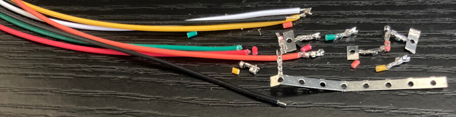 This picture is full of crimping fail.
I’ve spent several hours trying to crimp the HX20011 onto the AliEx cables that have JST-PH on the other end. And it could be that both of my hands are left. Or that I have crap crimpers (Engineer PA-09). Or lack of experience. Or maybe that the cables are actually too thin and crappy.
I. do. not. know.
But —
I’m not doing that.
Sorry LED strip, you’re stuck with JST-PH on your end, because this was torture.
Every time I crimped just one of the wires wrong, I had to start over the entire cable. Otherwise the other wires would be too long, and the whole thing would look ugly.
Nope.
Next time imma let the pros handle this (see the link above), even at 10 cables scale.
Antenna holder
This was also a part I thought would take no time at all.
Since I’m using an external antenna (Airgain N2420 they call it in the land of AliEx totally genuine parts), it shouldn’t be flapping in the wind.
My iterative process went roughly like this:
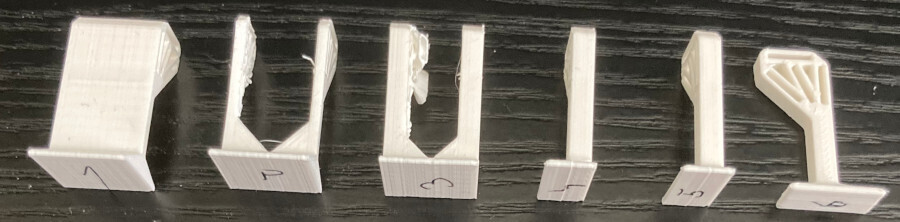 From downright ugly, through unprintable, to kinda ok.
In the end I settled on a piece that prints kinda nice (without supports), has four possibilities to place the antenna (0°, 22.5°, 45°, 90°), and takes a few minutes even on my really old printer:
The model is available in f3d, stl, step, if you want it.
Final assembly
With all the parts in place, it was time for final assembly and installation:
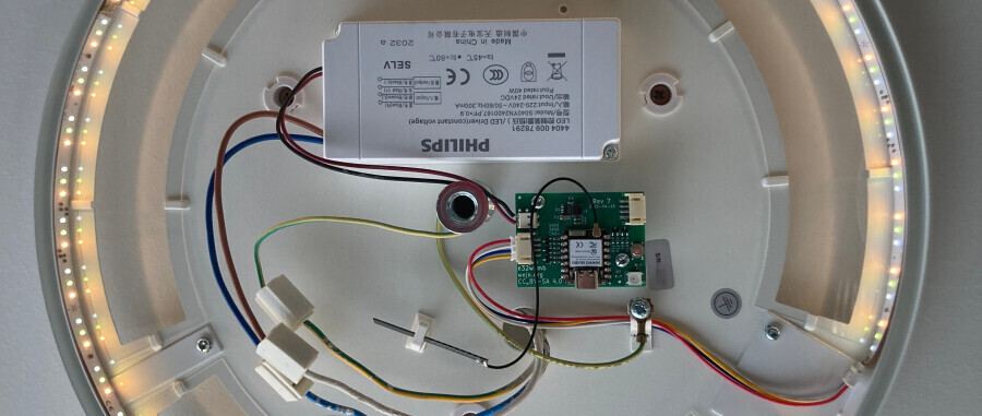
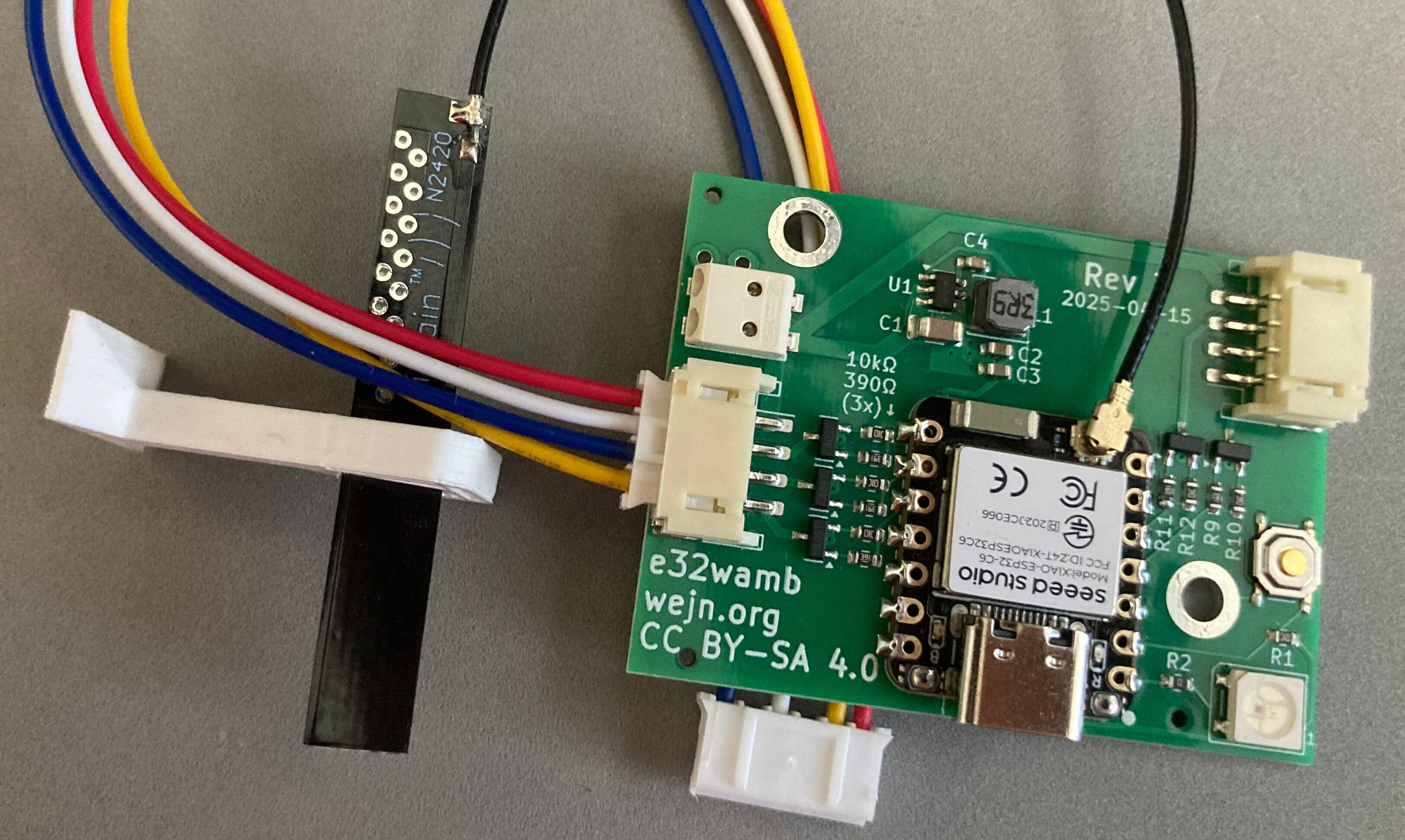 Final assembly (one unit).
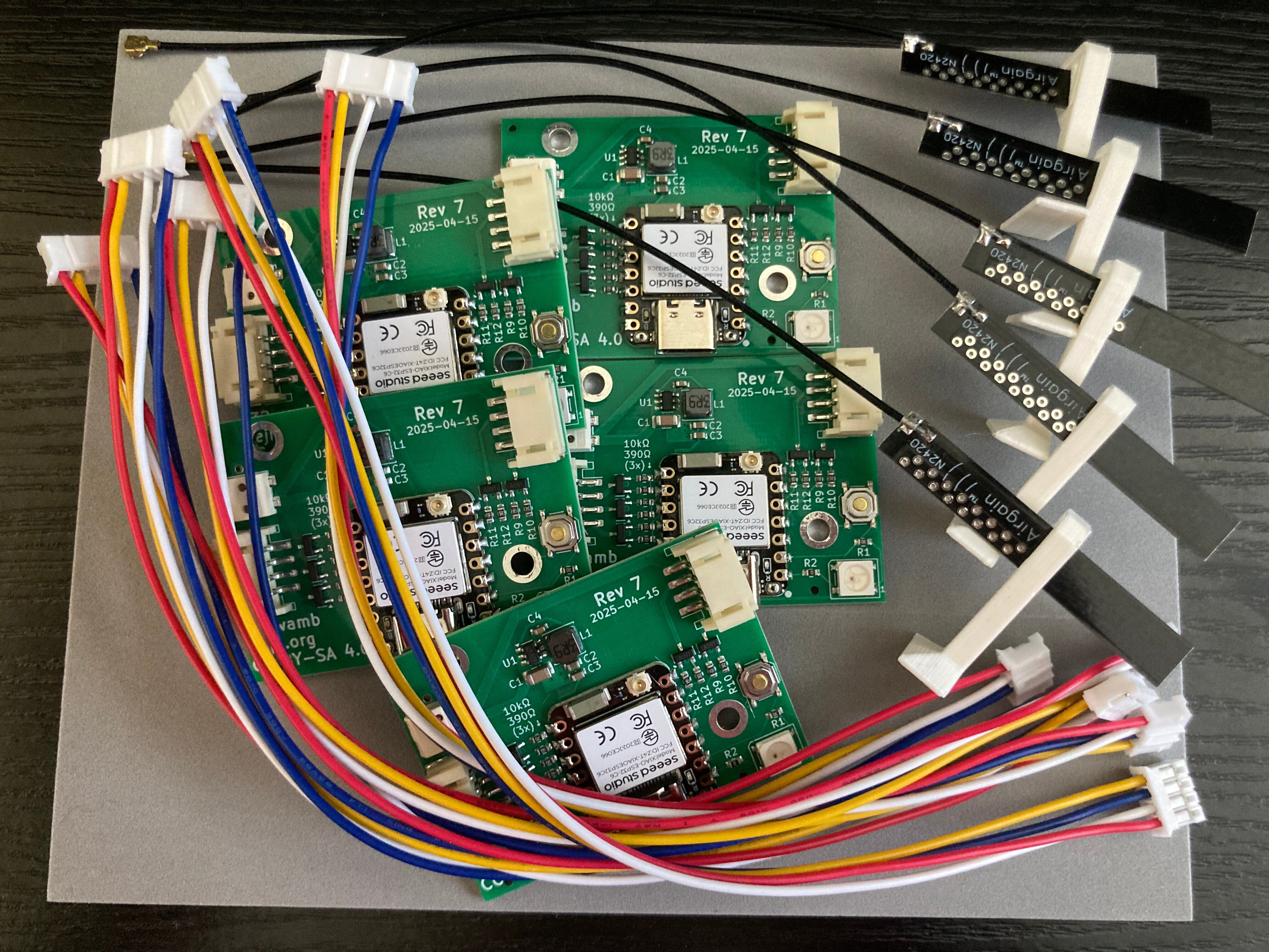 Install bundle.
and the money shot:
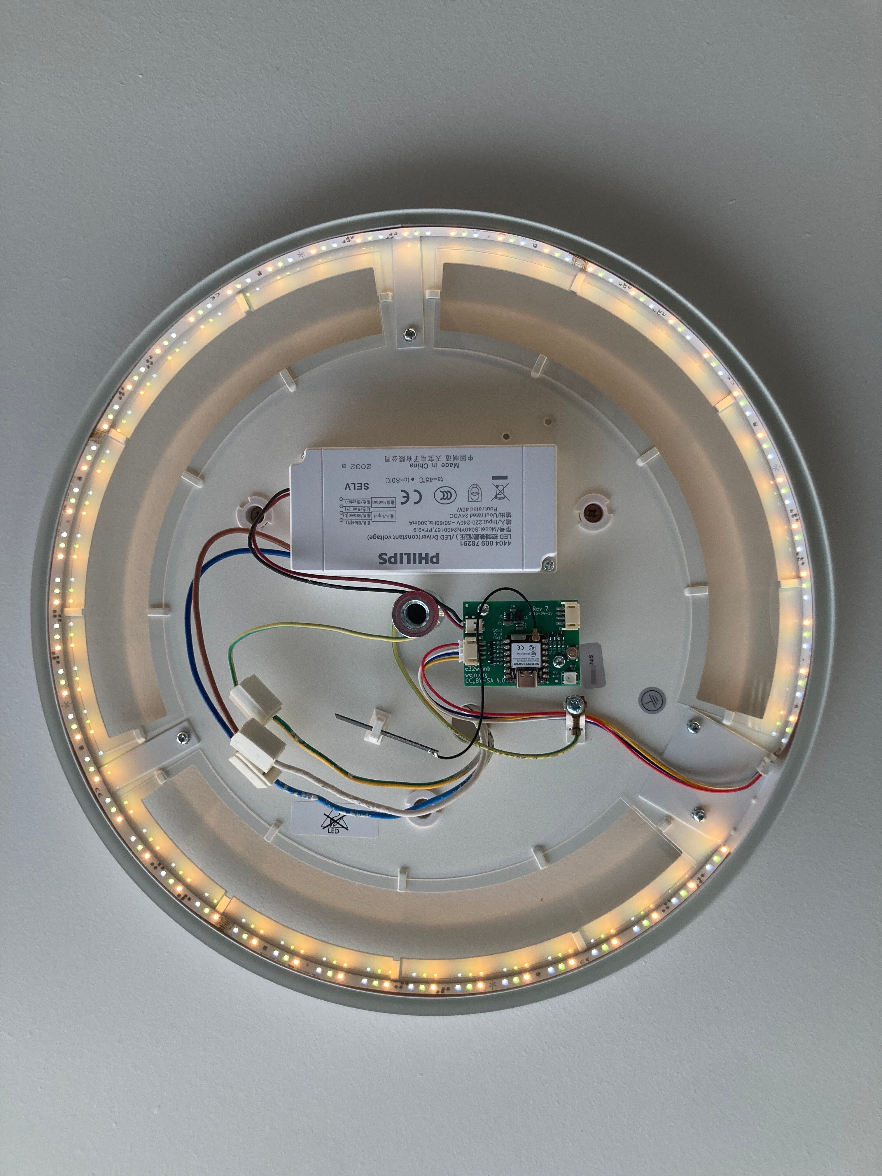 One of the e32wamb alive.
Closing words
The v1.0 of this was a long time coming. This is one of the “not because it was easy, but because I thought it would be easy” type of deals.
And there’s plenty to improve past this first version10. But – no lights in our flat are vulnerable to neighbor abuse anymore.
Yay!
-
I’m under the impression that the built in antennas, be it the SMD blocks or impedance-matched PCB traces, are pitiful little things with sub-par performance. ↩
-
Because as I said in the firmware, ya shall not use boot button for that. ↩
-
That would be KiCad 5; sometime in 2017 :-) ↩
-
Believe it or not, there is a line past which I value my time (and sanity) over a bit of extra cash spared. ↩
-
I thought the basic parts are not subject to the $1.5 per part loading fee, but they apparently are. ↩
-
Shit happens in real life, and having to rework a board because of a faulty component is something I wanted to avoid. ↩
-
Some say: Does not spark joy. ↩
-
One of the boards delivered has a short-to-ground defect that I only discovered after soldering on one of the XIAOs and powering the board up… which promptly fried something on the board. Sigh.
^WOh, look, a donor board. :) ↩ -
a.k.a. C703571 and C703565; it took me ages to figure this one out. ↩
-
Better animations / transitions, night mode, etc. ↩