Unbricking Ocean Optics Spectrometers
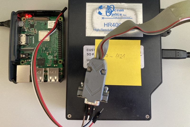 Unbricking HR4000 with a Raspberry Pi, using a breakout cable
Problem statement
During my Ocean Optics USB-DT adventures and the follow-up write-up of the I²C bug I managed to brick both HR4000 and USB4000 spectrometers1.
This article explains how to flash firmware into an Ocean Optics spectrometer that doesn’t respond well to the official USB Devices: Recovering a Corrupted EEPROM procedure2.
This was tested on HR4000, USB4000, and partially on Flame-S3. It is almost certain it would work for USB2000 or USB2000+. If you have another model (especially newer ones), you’ll need to use your judgement whether it is feasible or not.
Overview
The plan is simple:
- Reliably connect to I²C bus
- Use a few lines of Python to backup (and then flash) the EEPROM
To perform this miracle healing, you will need:
- the patient (broken spectrometer);
- a Raspberry Pi (any version), or some other device that can speak I²C at
3.3 V; - either 3-4 female-female Dupont (jump) wires, or something like PCBite4; read on for specifics.
Note: The reason the following procedure is safe is because after the initial bootstrap (configuration of the Cypress FX2 from the EEPROM and accessory + temp chip initialization), there’s no traffic on the I²C bus. That is, unless you trigger it by some command via USB / serial. If there were constant traffic, you couldn’t do this (safely).
Let’s get physical
In order to do the rest, you need reliable connection to the I²C bus of the spectrometer.
Depending on the model, this is either:
- trivial (USB2000+, USB4000),
- slightly challenging (HR4000),
- or downright impossible (Flame-S)
… without opening the device (or using a breakout board for the “accessory” connector).
Why am I saying that?
The USB2000+ and USB4000 uses Samtec IPT1-111-01-S-D-RA connector, which has a rather wide pitch (2.54mm).
The HR4000 uses 3M Pak50 (P50-030P1-RR1-TG), which has 1.27mm pitch.
The Flame-S uses JAE DD4 with 0.4mm pitch, that is additionally marked “obsolete”, and thus unobtainium from normal distributors5.
And while you can quite easily interface with 2.54mm pitch (I’ll show you how), targeting the 0.4mm in a recessed DD4 is not something you’d want to do as long as you have other options.
So, let’s talk connection options for each.
USB4000 (and USB2000+)
As mentioned before, USB4000 (datasheet)
and USB2000+ (datasheet) use
Samtec IPT1-111-01-S-D-RA.
The USB2000+ / USB4000 devices have the following pinout:
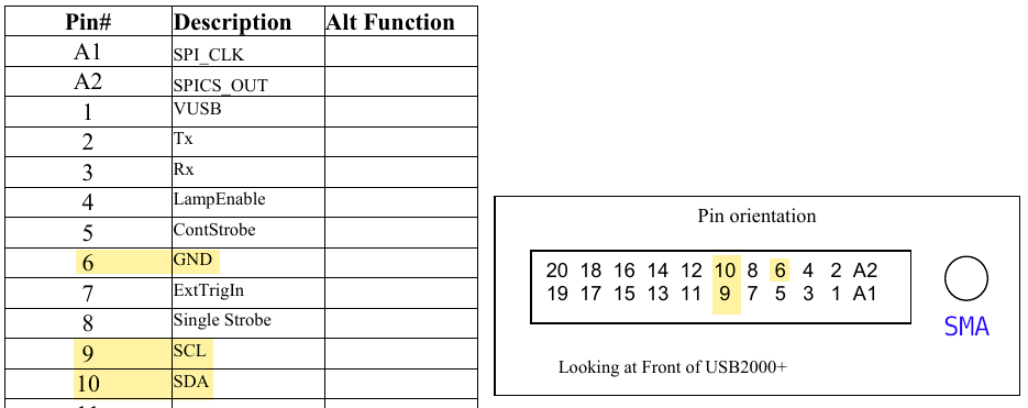 USB4000 / USB2000+ pinout
And given the pitch and size of the Samtec IPT1, it’s possible to strip down the female Dupont (jumper) wire from its sleeve and use that to connect:
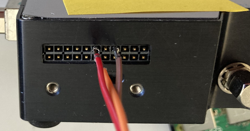 USB4000 dupont I²C connection: brown GND, red SDA, orange SCL
As far as I can tell, it doesn’t leave permanent marks, it is reliable enough to read out and write the EEPROM, and is secure enough to withstand normal manipulation.
Obviously, if you’re uncomfortable with that approach (especially the part where it’s powered on via USB), you can always open up the device, and connect to the EEPROM directly.
Unfortunately for us, in USB4000 the 24LC256 EEPROMs are on the PCB side that is facing optics.
If you open the USB4000, you get to see the following:
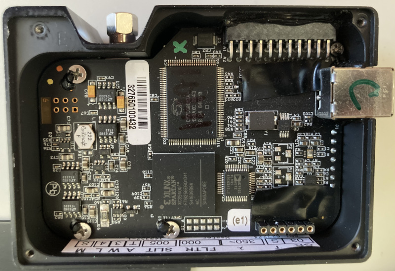 USB4000 with the lid off
If you look closely, though, you will find the following U3 fellow close to
the USB port (labeled 1721):
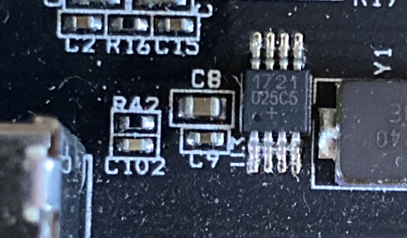 USB4000: close-up of the U3 (DS1721)
That’s a DS1721 digital thermometer chip.
So if you’re squeamish about connecting to the header with the Dupont hack6,
and don’t want to unscrew the PCB (because that might drift the optical
alignment), you could use the following pins of the DS17217:
- 1: SDA
- 2: SCL
- 4: GND
HR4000
The HR4000 (datasheet) has the following pinout:
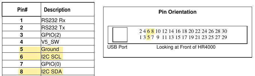 HR4000 pinout
Connecting to HR4000 is very easy with the breakout cable I described in the
USB-DT post
(and pictured above in the hero image).
But I assume you don’t have that cable (or P50-030S-EA or similar part) just
lying around.
In that case, you could try and interface with the connector using PCBite:
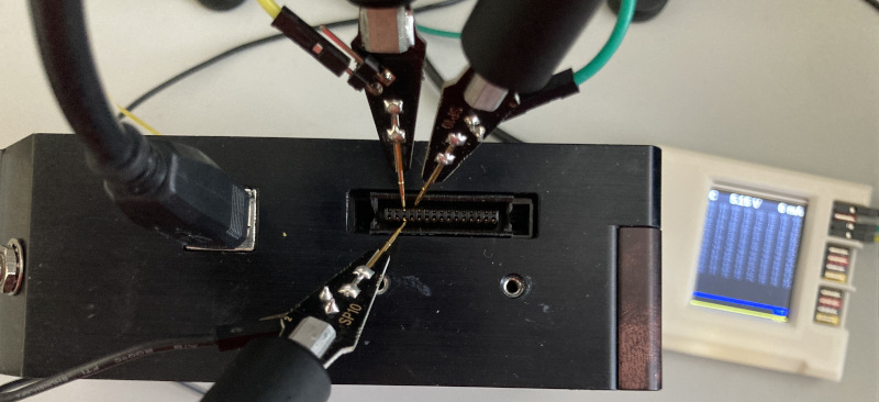 HR4000 via PCBite
If that doesn’t float your boat, then opening it up is actually good second option:
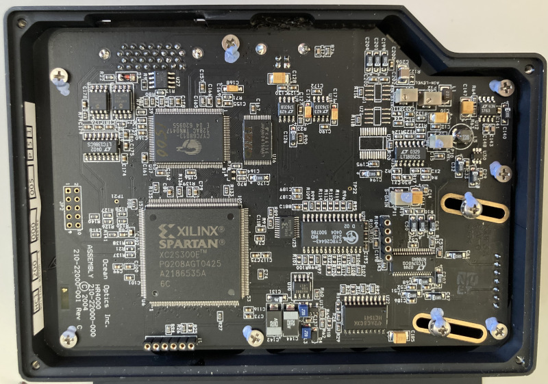 HR4000 without lid
On the top left side you find the two 24LC256 EEPROMs
(datasheet):
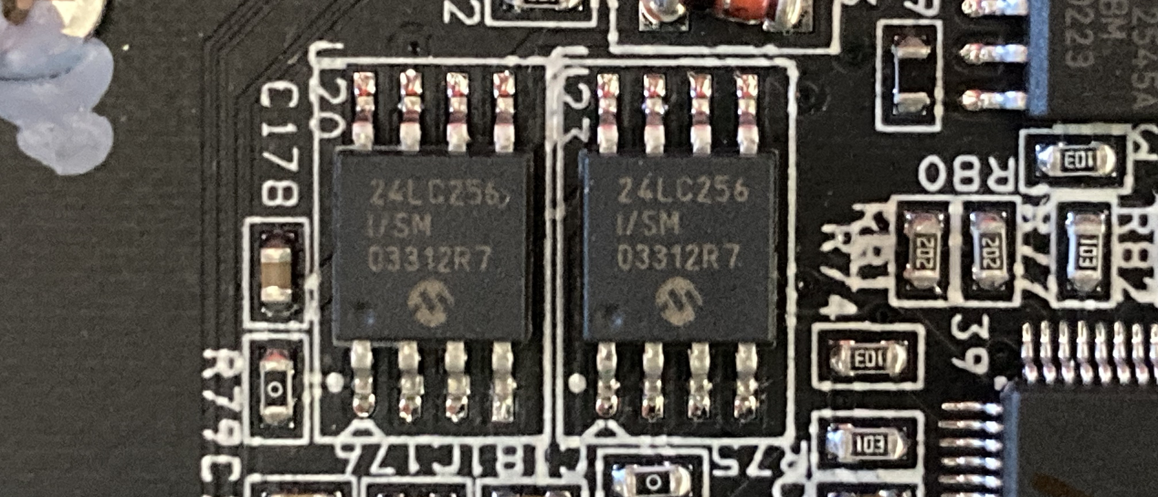 HR4000: close-up of the 24LC256
Connecting to either of them will do the trick; relevant pins:
- 4: GND
- 5: SDA
- 6: SCL
- 8: 3V3 (if standalone – without USB power)
Flame-S
Actually, here you’re on your own.
The FLAME-S datasheet / manual lists the DD4 pins as:
- 1: GND
- […]
- 20: GND
- 21: SCL
- 22: SDA
- 23: GND
but I have no need to open my Flame up, and I couldn’t find any pictures of the PCB.
So, either you have a breakout, or best luck on the inside8…
After opening it, search for DS1721 or 24LC256 on the board, and connect
to them in a similar fashion described above.
And with that, let’s talk about the other side.
The other side (of the connection)
In the beginning I alluded to the fact you need a Raspberry Pi (or any other I²C capable device).
If you get a Raspberry Pi, the following pins are of interest:
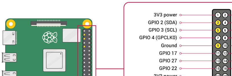 Raspberry Pi GPIO pins (relevant to I²C), from RPi documentation, Raspberry Pi Ltd, used under CC-BY-SA
To cut the prose short, you connect GND-GND, plug in the spectrometer to USB (can be the USB on the Raspi), then you connect SCL-SCL, and finally SDA-SDA.
If you’ve done that, then the last step is the actual dump / flash.
Software
Depending on what OS you run on the Raspberry, you might need to enable
I²C. If you have Raspi OS (and thus raspi-config utility), then
Options → I2C → Yes. Followed by reboot. If you’re a bit more low-level
(e.g. you use Alpine Linux like I do), you need dtparam=i2c_arm=on
in your usercfg.txt9, then a reboot.
Afterwards make sure the appropriate kernel modules are loaded:
modprobe i2c-dev
modprobe i2c-bcm2835
After which you need tools and libraries:
# Raspi OS
sudo apt install -y i2c-tools python3-smbus
sudo pip3 install smbus2

# Alpine Linux
apk add i2c-tools py3-smbus py3-pip
pip install smbus2 --break-system-packages
With that out of the way, time to probe the I²C bus:
$ i2cdetect -y 1
     0  1  2  3  4  5  6  7  8  9  a  b  c  d  e  f
00:                         -- -- -- -- -- -- -- --
10: -- -- -- -- -- -- -- -- -- -- -- -- -- -- -- --
20: -- -- -- -- -- -- -- -- -- -- -- -- -- -- -- --
30: -- -- -- -- -- -- -- -- -- -- -- -- -- -- -- --
40: -- -- -- -- -- -- -- -- -- -- -- -- -- -- -- 4f
50: -- 51 -- 53 -- -- -- -- -- -- -- -- -- -- -- --
60: -- -- -- -- -- -- -- -- -- -- -- -- -- -- -- --
70: -- -- -- -- -- -- -- --
You should be getting at least 0x4f (DS1721 temperature sensor)
and 0x51 (24LC256 with firmware and EEPROM slots).
The 0x53 is another 24LC256 that holds the irrad_cal data.
Otherwise, check your wiring.
If you got this far, you’re almost home.
I give thee two python scripts:
An EEPROM dumper:
eeprom_dump.py (click to expand)
#!/usr/bin/env python3
"""Dump a 24LC256 I2C EEPROM (32KB, 15-bit addressing) to a binary file."""

import argparse
import sys

from smbus2 import SMBus, i2c_msg

EEPROM_SIZE = 32768  # 24LC256: 256Kbit = 32KB
READ_CHUNK = 64


def dump_eeprom(bus_num: int, addr: int, size: int, chunk: int) -> bytes:
    data = bytearray()
    with SMBus(bus_num) as bus:
        for offset in range(0, size, chunk):
            n = min(chunk, size - offset)
            addr_hi = (offset >> 8) & 0xFF
            addr_lo = offset & 0xFF
            write = i2c_msg.write(addr, [addr_hi, addr_lo])
            read = i2c_msg.read(addr, n)
            bus.i2c_rdwr(write, read)
            data.extend(bytes(read))
    return bytes(data)


def main() -> None:
    parser = argparse.ArgumentParser(description="Dump a 24LC256 I2C EEPROM to a file")
    parser.add_argument("output", help="output binary file")
    parser.add_argument("--bus", type=int, default=1, help="I2C bus number (default: 1)")
    parser.add_argument(
        "--addr",
        type=lambda x: int(x, 0),
        default=0x50,
        help="7-bit I2C address (default: 0x50)",
    )
    parser.add_argument(
        "--size",
        type=lambda x: int(x, 0),
        default=EEPROM_SIZE,
        help="bytes to dump (default: 32768)",
    )
    parser.add_argument(
        "--chunk",
        type=int,
        default=READ_CHUNK,
        help="bytes per I2C transaction (default: 64)",
    )
    args = parser.parse_args()

    try:
        data = dump_eeprom(args.bus, args.addr, args.size, args.chunk)
    except OSError as e:
        print(f"I2C error: {e}", file=sys.stderr)
        sys.exit(1)

    with open(args.output, "wb") as f:
        f.write(data)

    print(f"Wrote {len(data)} bytes to {args.output}")


if __name__ == "__main__":
    main()
and an EEPROM flasher:
eeprom_flash.py (click to expand)
#!/usr/bin/env python3
"""Flash a 24LC256 I2C EEPROM (32KB, 15-bit addressing, 64-byte pages)
from a binary file, with post-write verification."""

import argparse
import sys
import time

from smbus2 import SMBus, i2c_msg

EEPROM_SIZE = 32768
PAGE_SIZE = 64
WRITE_TIMEOUT = 0.1  # seconds to poll for write cycle completion


def wait_write_complete(bus: SMBus, addr: int, timeout: float = WRITE_TIMEOUT) -> None:
    deadline = time.monotonic() + timeout
    while time.monotonic() < deadline:
        try:
            bus.i2c_rdwr(i2c_msg.write(addr, []))  # ACK poll: NAKs until write cycle done
            return
        except OSError:
            time.sleep(0.0005)
    raise OSError(f"EEPROM write did not complete within {timeout}s")


def write_page(bus: SMBus, addr: int, offset: int, data: bytes) -> None:
    addr_hi = (offset >> 8) & 0xFF
    addr_lo = offset & 0xFF
    msg = i2c_msg.write(addr, [addr_hi, addr_lo] + list(data))
    bus.i2c_rdwr(msg)
    wait_write_complete(bus, addr)


def read_bytes(bus: SMBus, addr: int, offset: int, n: int) -> bytes:
    addr_hi = (offset >> 8) & 0xFF
    addr_lo = offset & 0xFF
    write = i2c_msg.write(addr, [addr_hi, addr_lo])
    read = i2c_msg.read(addr, n)
    bus.i2c_rdwr(write, read)
    return bytes(read)


def flash_eeprom(bus_num: int, addr: int, data: bytes) -> None:
    with SMBus(bus_num) as bus:
        offset = 0
        total = len(data)
        while offset < total:
            page_remaining = PAGE_SIZE - (offset % PAGE_SIZE)
            n = min(page_remaining, total - offset)
            write_page(bus, addr, offset, data[offset:offset + n])
            offset += n


def verify_eeprom(bus_num: int, addr: int, data: bytes, chunk: int = 64) -> bool:
    with SMBus(bus_num) as bus:
        offset = 0
        total = len(data)
        while offset < total:
            n = min(chunk, total - offset)
            read_back = read_bytes(bus, addr, offset, n)
            expected = data[offset:offset + n]
            if read_back != expected:
                i = next(j for j in range(n) if read_back[j] != expected[j])
                print(
                    f"Mismatch at offset 0x{offset + i:04X}: "
                    f"wrote 0x{expected[i]:02X}, read 0x{read_back[i]:02X}",
                    file=sys.stderr,
                )
                return False
            offset += n
    return True


def main() -> None:
    parser = argparse.ArgumentParser(
        description="Flash a 24LC256 I2C EEPROM from a binary file, with verification"
    )
    parser.add_argument("input", help="input binary file")
    parser.add_argument("--bus", type=int, default=1, help="I2C bus number (default: 1)")
    parser.add_argument(
        "--addr",
        type=lambda x: int(x, 0),
        default=0x50,
        help="7-bit I2C address (default: 0x50)",
    )
    parser.add_argument(
        "--no-verify", action="store_true", help="skip post-write verification"
    )
    args = parser.parse_args()

    with open(args.input, "rb") as f:
        data = f.read()

    if len(data) > EEPROM_SIZE:
        print(
            f"Error: input is {len(data)} bytes, EEPROM is {EEPROM_SIZE} bytes",
            file=sys.stderr,
        )
        sys.exit(1)

    try:
        flash_eeprom(args.bus, args.addr, data)
    except OSError as e:
        print(f"I2C error during write: {e}", file=sys.stderr)
        sys.exit(1)

    print(f"Wrote {len(data)} bytes")

    if not args.no_verify:
        try:
            ok = verify_eeprom(args.bus, args.addr, data)
        except OSError as e:
            print(f"I2C error during verify: {e}", file=sys.stderr)
            sys.exit(1)
        if not ok:
            print("Verification FAILED", file=sys.stderr)
            sys.exit(1)
        print("Verification OK")


if __name__ == "__main__":
    main()
They are used exactly as you would expect:
# Dump the 0x51 (firmware + EEPROM slots)
$ python eeprom_dump.py --addr 0x51 0x51.bin
Wrote 32768 bytes to 0x51.bin

# Dump the 0x53 (irrad_cal)
$ python eeprom_dump.py --addr 0x53 0x53.bin
Wrote 32768 bytes to 0x53.bin

# Flash the proper firmware
$ python eeprom_flash.py --addr 0x51 HR4000v2230nonAChip.iic
Wrote 17203 bytes
Verification OK
Not much to it, in the end10. But please: first backup whatever was in the EEPROM, only then flash. You never know if it proves useful down the road. And the file is laughably small.
Closing words
I think the trickiest part of this whole adventure is the physical setup. The pins are small, and thus easy to fat finger a disaster.
With a bit of magnification, and proper EEPROM dump first, there isn’t that much to go wrong.
-
Insert “because we’re smart” meme here. ↩
-
Whose tldr is: short the
SDApin, plug in the spectrometer, use OO’s “USB EEPROM Programmer” utility. ↩ -
Where I just verified the I²C addresses are the same; using another (unpublished) script that dumps data using the
seabreezeraw_usb_bus_accessfeature (with0x60and0x61commands). ↩ -
There are budget options; see your favorite Chinesium merchant. ↩
-
Neither Mouser nor Digikey have them; some Chinese suppliers would love to sell you some, at $25-$90 per connector (quoted at 10 pc qty). ↩
-
But if you are, explain yourself… ↩
-
I haven’t tried supplying power via the pin 8 (VDD), but maybe that would also power the 24LC256 on the other side of the PCB? ↩
-
And if you do open it up, send me a few pictures, will you? ↩
-
/media/mmcblk0p1/usercfg.txtto be more precise ↩ -
If you’re wondering about the
nonAChipvsAChipfor HR4000 firmware, I actually randiff -u <(xxd 0x51.bin) <(xxd HR4000v2230nonAChip.iic)and determined, thatnonAis mine, because the diff was smaller than in theAcase. Highly scientific™. ↩