Hue Engine: Basic reconnaissance
Introduction
This is the first post in the Reversing Philips Hue light driver series.
Problem statement
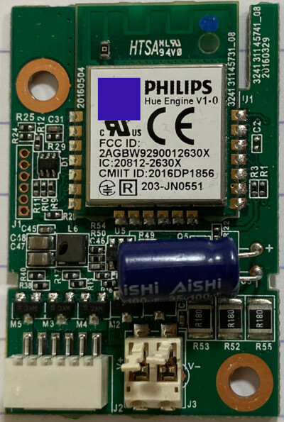
We have an unknown PCB board labeled “Philips Hue Engine v1.0”:


What can we quickly find out about it?
Quick search
I think the FCC ID (2AGBW9290012630X) is the single most useful thing on the board.
Because it will almost instantly give you low-resolution pictures from the FCC data:
I have cached the PDFs here:
There’s more on those two websites, but this will do.
Pinouts
Front
Looking at the front, there are several headers worth talking about.
The one on the left (J1), from the top down:
- GPIO (chip 9)
- SCL (chip 4)
- SDA (chip 5)
- GPIO1 (chip 6)
- VDD (chip 15)
- GND
The one on the bottom (J2), left to right:
- Pin13 (via mosfet), NC to strip
- Pin11 (via mosfet), goes to strip’s
C - Pin10 (via mosfet), goes to strip’s
G - Pin9 (via mosfet), goes to strip’s
F - Pin12 (via mosfet), NC to strip
- VBUS (24V)
Then there’s the chip itself. The manual is quite clear about pin number to actual pin, but it’s too low resolution to say. To save you the trouble:
Left row, top to bottom:
- 1, GND
- 2, ADC2
- 3, ADC1
- 4, Mix1
- 5, Mix2
- 6, GPIO1
- 7, GPIO2
Bottom row, left to right:
- 8, Enable
- 9, PWM0 (Green) – “warm” channel for white ambiance
- 10, PWM1 (Blue) – “normal” channel for white ambiance
- 11, PWM2 (Warm white) – “cold” channel for white ambiance
- 12, PWM3 (Red)
- 13, PWM4 (Cold white)
Right row, top to bottom:
- 20, SWDIO
- 19, SWCLK
- 18, Nrst
- 17, RXD
- 16, TXD
- 15, VDD (3.3V)
- 14, GND
Back
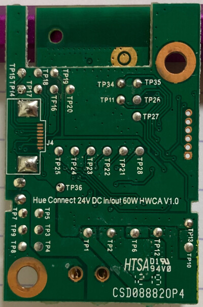
On the back is the prominently unpopulated J4 header, top to bottom:
- TP14, SWCLK
- TP15, SWDIO
- TP17, TXD
- TP18, RXD
- TP16, Nrst
- NC
- TP19, VDD
- TP20, GND
I did not care to map the rest of the test points, but it’s relatively visible from the PCB.
Update 2025-02-09: Since I wanted easy access to the PWM pins, I probed the test points on the back. Turns out:
- TP28, pin8 (Enable)
- TP21, pin9 (PWM0) – “warm” channel for white ambiance
- TP22, pin10 (PWM1) – “normal” channel for white ambiance
- TP23, pin11 (PWM2) – “cold” channel for white ambiance
- TP24, pin12 (PWM3)
- TP25, pin13 (PWM4)
Million dollar question – does it SWD / JTAG?
Nope1.
I don’t know what the chip is, but the debug port is either locked, or needs some specific procedure to become available2.
Since I don’t want to remove the metal can, I gave up at this point.
But the UART was chatty:
[Log,Info,S_LightConfiguration,Configuration Data OK, crc=0x9557C3C5]
[Log,Info,S_DeviceInfo,Default Flux table]
[Log,Info,S_DeviceInfo,ProductId: ENA_LTC001_1_BeingCeiling_v1, ModelId: LTC001]
[Log,Info,S_DeviceInfo,ZLLDeviceId: 544(ColorTemperatureLight), PwmChnl: 3]
[Log,Info,D_LoadMeasurement,Vbus=2941, calMask=30303]
[Log,Info,ModuLum,devsig=0x10010318]
[Log,Info,S_DeviceInfo,Booting into normal mode...]
[Log,Info,S_DeviceInfo,DeviceId: ConfLight]
[Log,Info,N_Security,LIB4.6.135]
[Log,Info,N_Security,KeyBitMask,0x0012]
[Log,Info,AL_OTAUpgrade,containerVersion=0x01000700]
[Log,Info,ModuLum,errs=0,lastErr=PWRON@0]
[Log,Info,ModuLum,Platform 0.85.0: r20342, BC_V3.3.0_2.4_M: r20342]
[Log,Info,ModuLum,Product version ConfLight fw_ver: 1.16.1_r19181,built by LouvreZLL]
[Log,Info,A_Commissioning,NwkAddr: 0x..., Ch: 25, Pan: 0x..., NwkUpdId: 0, ExtPanID: ...]
[TH,Ready,0]
[Log,Info,S_XNv,CompactSector(s=6)]
[Log,Info,N_Connection,Starting discovery for updated networks]
[Log,Info,N_Connection,Discovery for updated networks completed]
What is very curious is the [Log,Info,D_LoadMeasurement,Vbus=2941, calMask=30303]
line.
Because if you power the module from 24V, you get: [Log,Info,D_LoadMeasurement,Vbus=24014, calMask=30303].
So, yes, the module somehow measures VBUS. Whether that’s used for anything is unclear.
Conclusion
For me, this is a clear fail in the “dump and quickly mod the firmware” department.
I’m sure someone like LimitedResults could make a quick job of this. But man, do I not want to sink any more time into this approach.
So, onwards with the “get enough information to recreate the controller” – in the next post.
-
At least not easily. You might be more skilled than I am. In which case, teach me, Master. ↩
-
And funny thing is, in the old
9290019684version that usesEFR32MG13(see the intro post for more info), the debug port at least responds to basic SWD probing. Because I was able to find it with a Flipper originally. ↩